
China Split Butterfly Valve: A Complete Guide to Design and Applications
2026-08-14
If you've ever wrestled with a bulky valve in a tight piping run, you know the pain. China split butterfly valves solve that headache with a two-piece body that simplifies installation and maintenance—no need to dismantle the whole line. But not all split butterfly valves are equal, and choosing the wrong design can lead to leaks, pressure loss, or early failure. This guide cuts through the noise, breaking down key design features, material choices, and real-world applications so you can spec with confidence. And when you're ready to source, AVM offers a range of proven split butterfly valves built for demanding industrial environments. Let's get into the details.
The Split Body Advantage and How It Improves Sealing
Most valve bodies are cast as a single piece, which works fine until something inside needs attention. A split body takes a different route: two halves are bolted together around the internal components, and that simple change opens up real sealing advantages. Because the halves can be machined independently, the mating faces achieve a flatter, more consistent contact. The gasket or seal ring then compresses evenly, eliminating the kind of uneven loading that leads to early weepage.
Under shifting temperatures or pressure spikes, a one-piece body has nowhere to absorb dimensional changes. The split design, by contrast, allows the joint to breathe slightly while the bolts hold the assembly in tension. That controlled movement keeps the sealing surfaces in alignment instead of forcing them to warp or gap. In services with frequent thermal cycling, this often translates into fewer leak points and a valve that stays tight long after installation.
There is also a practical side to the split body advantage. When the internal sealing elements eventually wear, you can unbolt the two halves, replace the seat or seal, and reassemble without cutting the valve out of the line. That accessibility means routine maintenance is more likely to happen on schedule, which in turn helps preserve the original sealing performance rather than letting small leaks develop into bigger problems.
Choosing Seat Materials for Abrasive and Corrosive Media
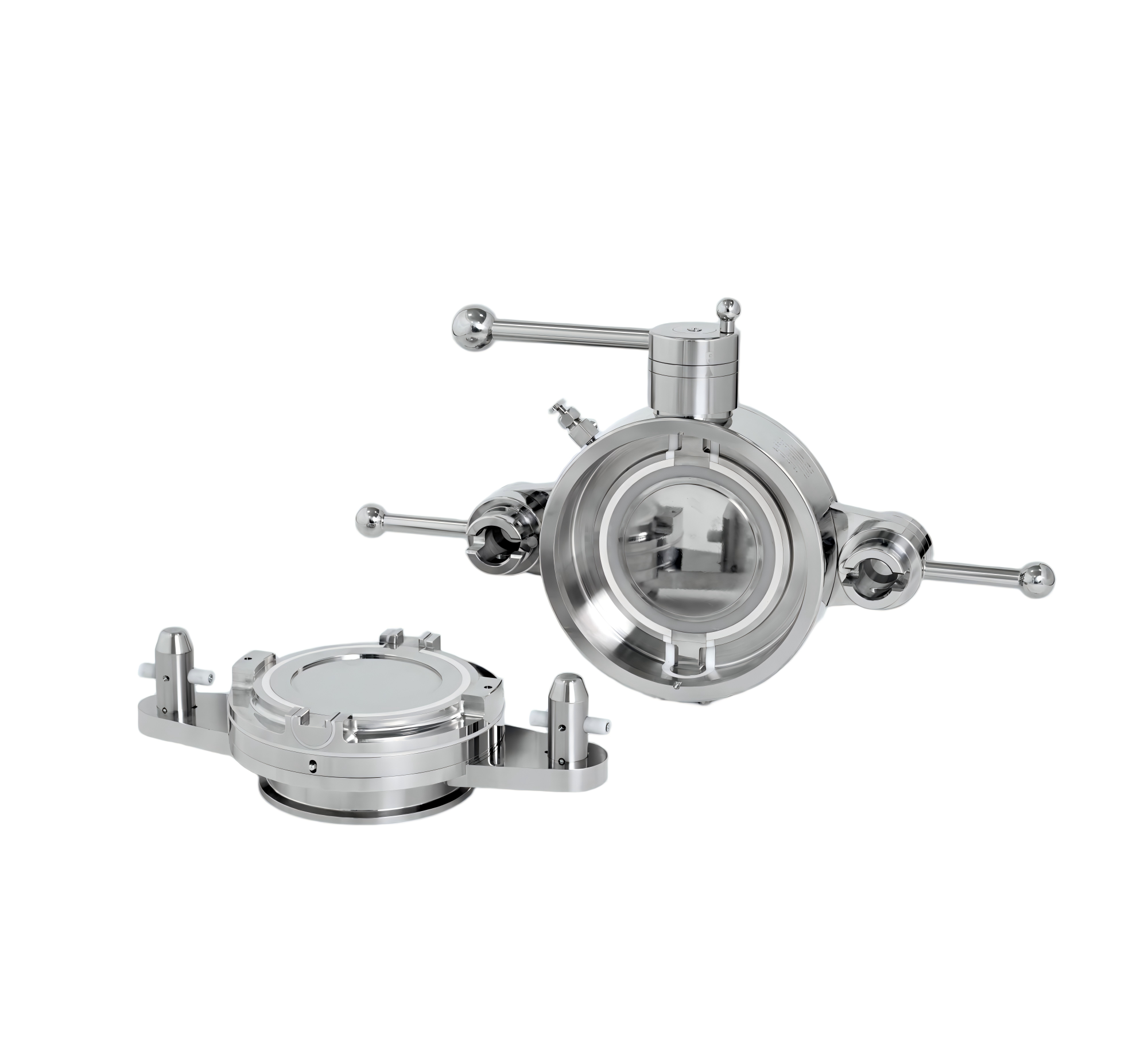
When a valve seat faces abrasive slurries or acidic process fluids, the usual stainless steel or PTFE options quickly show their limits. Hardened alloys like Stellite or tungsten carbide resist erosion from particles, but they can still suffer chemical attack in aggressive environments. A more practical approach is to evaluate the specific wear mechanism first: if the media cuts or grinds, hardness dominates; if it dissolves or pits the surface, chemical compatibility takes priority. Sometimes a ceramic seat such as alumina or silicon carbide offers both, though brittleness must be considered.
For highly corrosive streams with moderate solids, fluoropolymer-based seats—PFA or modified PTFE—often outperform metal seats because they handle a wide pH range while providing some resilience to particle impact. However, soft seats can deform under high pressure or temperature, leading to leakage. A middle ground is a metal seat with a hard coating, like chrome carbide or nickel-based overlays, which protects the base material from both abrasion and corrosion. Operators should also look at the seat geometry: a slightly wider contact area can reduce localized stress and extend service life in demanding media.
Field experience shows that no single seat material works for every abrasive-corrosive combination. Testing small samples in actual process conditions, rather than relying solely on datasheets, often reveals unexpected interactions—for instance, a seat that handles pure acid well may fail quickly when fine sand is present. Pairing the seat with a compatible disc or ball material matters just as much; dissimilar hardness can cause one component to wear prematurely. Ultimately, selecting the right seat means balancing hardness, chemical resistance, thermal stability, and cost, then validating that choice through pilot runs or historical performance data from similar services.
Real Applications from Water Treatment to Petrochemical Plants
Across both ends of the industrial spectrum, equipment originally designed for clean-water duty gets repurposed in ways that surprise even seasoned engineers. A municipal plant in Arizona, for instance, replaced sand filters with ceramic membranes to handle arsenic spikes after monsoon runoff—the same membrane geometry now shows up in produced-water recycling on shale pads. In petrochemical settings, the real test isn't the design spec but how a pump or valve behaves after six months of exposure to chlorides, H2S, and abrasive catalyst fines. Field data from a Louisiana ethylene cracker showed that upgrading seal flush plans cut unplanned downtime by 40%, a figure no lab test would have predicted.
Water treatment applications rarely make headlines, but they quietly determine whether a facility stays in compliance. At a desalination plant in Carlsbad, California, operators learned that switching antiscalants from a phosphonate blend to a carboxylate-based polymer extended membrane life by 18 months, simply because the new chemistry tolerated higher silica levels. Cooling towers in refineries face a different beast: biofilm-induced under-deposit corrosion, which often goes unnoticed until a heat exchanger fails. Real-world fixes include staggered biocide dosing and installing side-stream filtration that captures particles below 5 microns—measures that sound mundane but save millions in lost production.
Petrochemical plants push materials to their limits, and the difference between a textbook solution and a field-proven one becomes obvious fast. A gas processing facility in West Texas dealt with recurring leaks in amine contactor towers until engineers swapped standard 316 stainless internals for a duplex alloy—not because of the nominal corrosion rate, but because chloride stress corrosion cracking had been misdiagnosed for years. In another case, a polypropylene unit in Singapore reduced catalyst plugging in loop reactors by changing the reactor slurry pump impeller clearance from 0.8 mm to 0.5 mm, a tweak discovered only after analyzing wear patterns on pulled pumps. These are the kinds of fixes you won't find in a vendor brochure.
Decoding Pressure and Temperature Limits for Daily Operations
Reading pressure and temperature limits isn't just about matching numbers on a screen to a spec sheet. In daily work, those numbers shift with ambient conditions, equipment wear, and changes in fluid composition. Operators learn to treat the posted maximums as boundaries within a broader operating envelope rather than hard trip points. A gauge that creeps toward the high side on a summer afternoon may still be well within safe limits once you account for thermal expansion of the piping. Similarly, a pressure reading that looks normal at idle can hide dangerous spikes once flow resumes. Decoding these limits means knowing which variables are independent, which lag behind, and which sensors can be trusted.
Most effective teams build a simple, non-negotiable routine around pressure and temperature checks. They log baseline readings at the start of each shift, flag any drift beyond a narrow band, and cross-check against the asset’s rated service conditions. Instead of relying on memory, they keep a short list of the top three or four failure modes tied to overpressure or overheating for the specific unit. If a limit is approached, the response is already scripted: reduce load, verify cooling or relief paths, and isolate if necessary. The goal isn't to avoid every excursion—some processes naturally swing—but to recognize when a swing stops being normal and becomes a warning.
Installation and Alignment Tips That Prevent Early Failure
Most early bearing and coupling failures start with something as simple as a dirty mounting surface or a bolt pattern tightened in the wrong order. Before setting any machine in place, scrape off old gasket material, paint overspray, and rust from the base and feet. Use a straightedge and feeler gauges to check for gaps, then bring the surfaces into contact with thin, full-size shims rather than stacking multiple small ones. Tighten anchor bolts in a diagonal sequence and recheck torque after a few hours of operation—this catches the relaxation that happens after the first heat cycle.
Alignment is not a one-time measurement. After rough positioning, check for soft foot by loosening each hold-down bolt one at a time and sliding a 0.05 mm feeler under the foot. If it goes in, add shims until all feet sit flat without pulling the frame out of shape. Use a dial indicator or laser system across the coupling faces, but don't trust a single full-turn reading—rotate both shafts together and compare values at 12, 3, 6, and 9 o'clock. For machines that run hot, set the cold alignment to the manufacturer's thermal growth offsets, otherwise the shafts will move into a misaligned state once they reach operating temperature.
Finally, leave the coupling disconnected until the base is fully grouted and the final alignment is done. Pipe strain from forced flange bolt-ups can distort a perfectly aligned pump or gearbox, so support all connected piping independently and recheck alignment after the system is filled or pressurized. Record the final shaft positions and dial readings, then run the unit for a few hours and measure again while it's still warm. Small corrections at this stage are far cheaper than replacing a bearing or seal that failed because the machine was aligned cold and never verified hot.
Inspection and Replacement Intervals for Decades of Service
For equipment that has already logged twenty or thirty years, fixed replacement schedules from the original manual rarely tell the whole story. The real driver is how the asset has been used, not just how long it has existed. A gearbox that ran intermittently in a dry indoor plant may have decades of safe life left, while an identical unit exposed to coastal humidity or frequent starts and stops might need bearings swapped much earlier. Start by pulling the actual maintenance history and failure records, then compare that against the original manufacturer guidance. Any interval that has never caused a problem should probably be extended, but only after confirming through non-destructive checks that hidden wear is not accumulating.
Inspection intervals for aging infrastructure work best when they blend calendar time with measured condition. Rather than opening a critical valve every two years simply because the manual says so, use thermography, vibration signatures, oil analysis, or ultrasonic thickness readings to judge when internal wear is approaching a threshold. That approach reduces unnecessary teardowns, which themselves introduce risk, while still catching fatigue cracks, seal degradation, or insulation breakdown before they become failures. For components that cannot be inspected without destructive disassembly, set conservative replacement intervals based on the shortest service life observed in your own fleet, not generic industry averages.
Finally, treat the interval plan as a living document that gets revised after every major overhaul or unexpected failure. If a pump impeller eroded faster than predicted, shorten the inspection window for similar pumps and record the operating conditions that likely accelerated wear. If a pressure vessel has passed every hydrostatic test for thirty years with no wall loss, lengthening the next test interval may be justified, provided that operating pressure and temperature remain unchanged. This feedback loop, grounded in actual performance and local environment, is what allows critical systems to serve reliably for decades without either excessive downtime or hidden risk.
FAQ
A split butterfly valve has a body that separates into two halves, usually along the stem axis. This lets you remove the disc and seat without taking the whole valve out of the pipeline. You can service it in place, which saves a lot of downtime compared to wafer or lug styles that need full removal for seat replacement.
China has a dense supply chain for valve castings, machining, and elastomer seats. That concentration brings down cost while still allowing custom trim and coating options. Many Chinese factories also produce split bodies in duplex stainless or lined versions for corrosive service, which can be hard to find elsewhere at similar price points.
They are common in chemical processing, wastewater treatment, and HVAC systems where space is tight and inline maintenance matters. Any process that deals with abrasive slurries or frequent seat wear benefits because the split design allows a quick seat swap without breaking flanges. Power plants also use them on cooling water lines for the same reason.
Check the stem sealing arrangement. A good design uses a blowout-proof stem and a secondary seal, not just a single O-ring. The split joint should have a machined metal-to-metal stop or a captured gasket to prevent over-compression. Also look at the disc edge profile—rounded or polished edges reduce seat wear and lower torque.
The split body itself doesn't automatically lower the rating. It's the seat material and body bolts that usually set the limit. A well-made split butterfly valve can handle PN10 to PN25 or Class 150, and with metal seats up to 400°C or more. Just verify the flange drilling and bolt grade, because the body halves rely on those fasteners to maintain the seal.
Yes, and that's one of its strengths. The top flange can be machined to ISO 5211 dimensions for direct mounting of electric or pneumatic actuators. Since the split design often has lower breakout torque from a centered disc and good seat alignment, smaller actuators can be used, which cuts cost on larger valves.
Overtightening the split joint bolts is a big one—it deforms the seat and causes high torque. Another is using the wrong lubricant on the stem, which can swell elastomer seals. People also forget to cycle the valve periodically in slurry service, allowing solids to pack behind the seat. A simple half-open flush during shutdown helps a lot.
Conclusion
The China split butterfly valve stands out largely because its two-piece body clamps around the disc and shaft, distributing bolt load evenly and eliminating the stem-bore distortion common in one-piece castings. That split construction directly improves sealing: the seat ring is compressed uniformly along its circumference, so even slight pipeline misalignment won't open a leak path. For abrasive or corrosive service, seat selection matters as much as body design. PTFE and reinforced PTFE handle aggressive chemicals and temperatures up to roughly 180°C, while metal seats resist slurries and high-velocity solids that would quickly erode soft polymers. Elastomers like EPDM or NBR remain economical choices for clean water and mild acids, but swapping to a different seat without changing the valve body is what makes the split design so practical in the field.
Installed from municipal water treatment plants to petrochemical crackers, these valves perform reliably in throttling and isolation duties. Real applications show the same split body used on filter backwash lines, chemical dosing skids, and crude oil transfer headers, often with only a seat or actuator change between them. Pressure and temperature limits are not fixed single numbers; they shift with seat material, flange rating, and whether the valve sees full vacuum or thermal cycling. A common daily operating envelope is 16 bar and -10°C to 180°C, but for steam or hot oil it is wiser to derate according to the seat chart rather than guess. Installation and alignment deserve more attention than they typically receive. Leaving the disc slightly open during flange tightening, verifying concentricity with a feeler gauge, and supporting the pipe on both sides prevents the early failures that look like seal defects but are actually assembly errors. Inspection and replacement intervals then become predictable: soft seats often last five to eight years in clean water, while metal-seated versions in abrasive slurry may need quarterly checks but deliver two decades of service if the split body is opened, cleaned, and re-torqued correctly.
Contact Us
Contact Person: Ananda
Email: [email protected]
Tel/WhatsApp: 8619016718200
Website: https://www.wzaomi.com